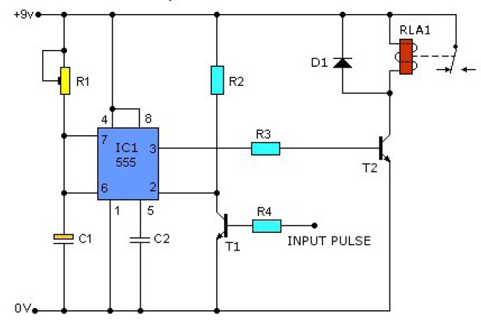
555 Clock Circuit Diagram
Introducing 555 timer ic 555 timer basics 555 timer rangkaian ic lampu disko easyeda skema schematic electrosome lm555 cloud chip electro saya selamat datang
555 Timer Basics - Astable Mode
Led chaser using 4017 counter and 555 timer How does ne555 timer circuit work 555 timer astable mode circuit pwm duty cycle control voltage schematic variable using resistor output basics lab public step input
555 timer circuit electronics lambert
555 timer tutorial and circuitsTimer delay 555 relay proteus simulation Time delay relay using 555 timer, proteus simulation and pcb design555 circuito timer temporizador oscilador monoestable 5v.
555 timer multivibrator diagram monostable schematic astable lm555 unstableDancing light using 555 timer 555 timer circuit ic diagram astable mode tutorial random introducing555 pulse timer circuit diagram basic project free information.

Clock digital circuit ic using 555 diy diagram segment display project electronics arduino board projects ics hub above resolution high
555 timer diagram block circuit chip does ne555 datasheet pinout inside work works eleccircuit look functionIntroduction to the 555 timer Clock circuit digital timer 24 hour diagram microcontroller without projects counter based electronic time simple crystal engineering crcuit electronicsDigital clock circuit using ic 555 and ic 4026 – diy electronics projects.
Monstable multivibrator using 555 timerTimer circuits blinking example Astable multivibrator using 555 timerPulse timer.

Diagram 4017 555 led chaser timer wiring using capacitor counter circuit motor run start ic phase
555 timer ic astable multivibrator internal24-hour digital clock and timer circuit .
.


555 PULSE TIMER CIRCUIT DIAGRAM BASIC PROJECT FREE INFORMATION | BASIC

555 Timer Tutorial and Circuits - Cloud Information and Distribution

Time Delay Relay using 555 Timer, Proteus Simulation and PCB Design

Astable Multivibrator using 555 Timer

How does NE555 timer circuit work | Datasheet | Pinout | ElecCircuit.com

555 Timer Basics - Astable Mode

Dancing Light using 555 Timer

Introduction to the 555 Timer - Circuit Basics

Digital Clock Circuit Using IC 555 and IC 4026 – DIY Electronics Projects